


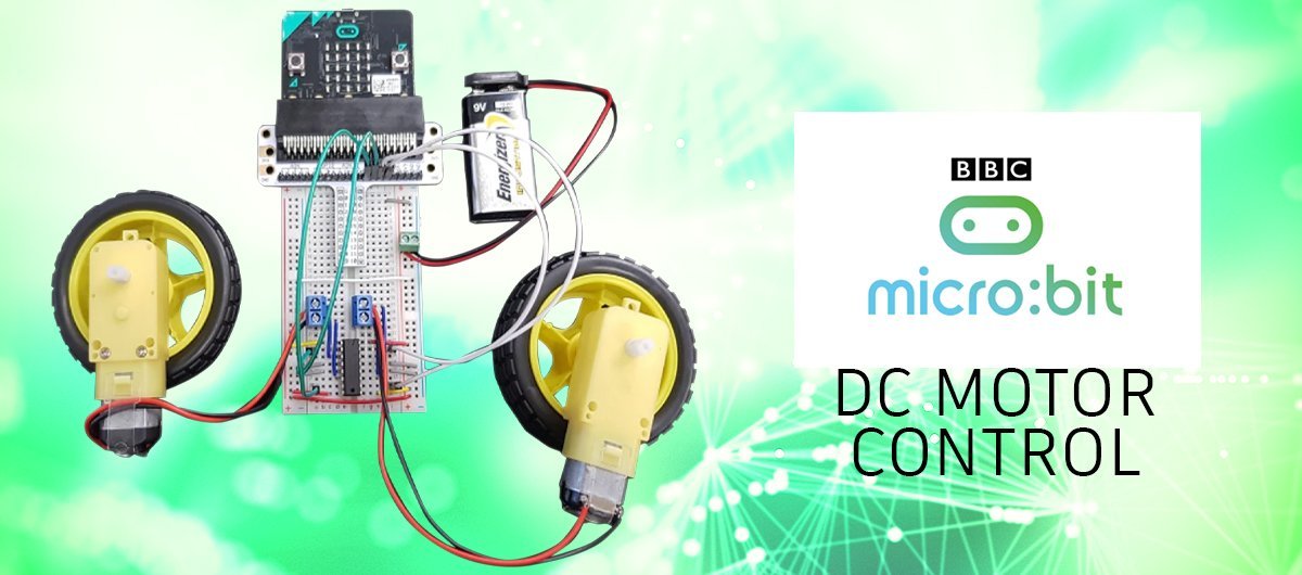
DC Motors
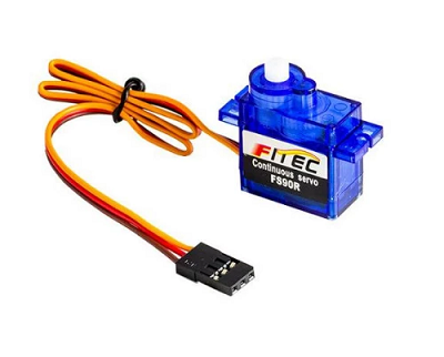
In this lesson, we will look at a couple of inexpensive hobby motors commonly used in educational robotics. The DC Motor takes the electrical energy and turns it into mechanical motion. These particular motors require about 3 volts to overcome the mechanical resistance and start turning. But you really need about 5 or 6 volts to give them enough power to turn happily.
You can not drive these motors directly from the micro:bit pins.
The most simple circuit you can use is a BJT transistor used as a switch, to effectively amplify your 3 volts from the micro:bit up to say five volts. This is just like experiment 4 in the Inventors Kit but with a bigger more powerful transistor like a TIP121. But you will only be able to drive your motor in one direction.
Controlling the Motors
For robotics, you will want your motor to be able to drive forward and reverse. This means you need to change the polarity across the motor. To drive forward you put say 5 volts on the red wire and 0 volts on the black. To drive backwards you put 0 volts on the Red wire and say 5 volts on the black. As you will not be physically swapping the wires over, you need some switches to do this.
The H Bridge
DC Motor direction control is achieved by using a circuit that looks like an H.
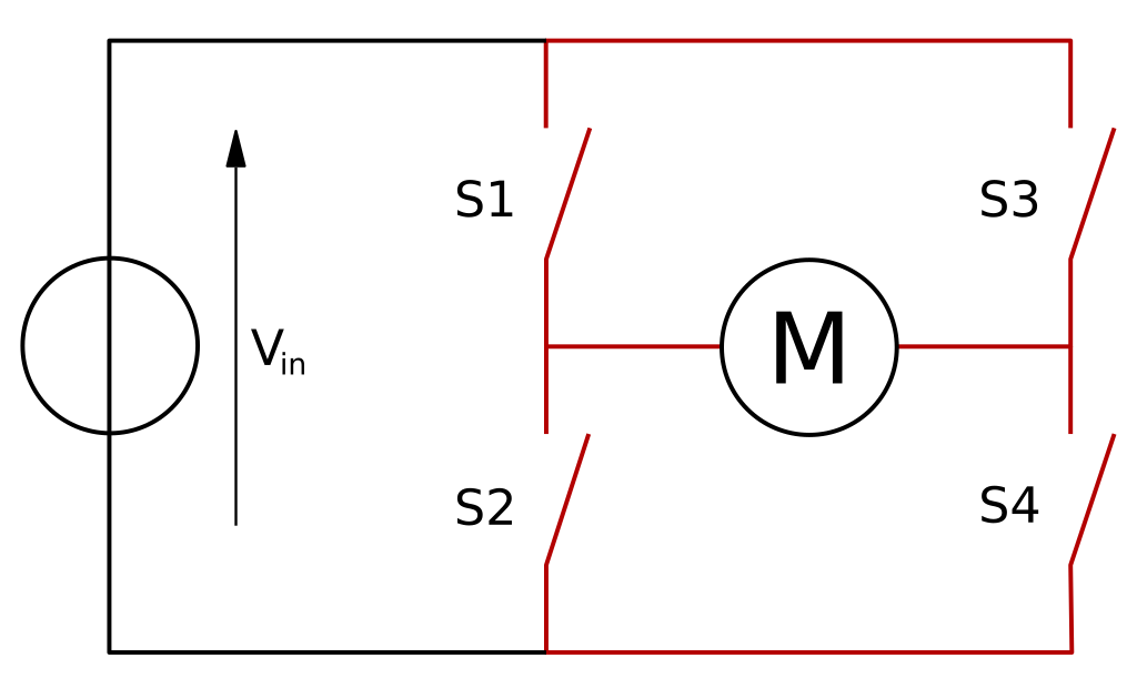
To drive the motor forward you turn on Switch 1 and 4. To drive the motor in reverse you turn on Switch 2 and 3. Now if you build this circuit with MOSFET's be sure not to turn on switch 1 and 2 or switch 3 and 4 together as you will have a short circuit!
An alternative to using four discrete components here is to use an Integrated Circuit that can do this for you. These IC's also offer some other benefits, like preventing short circuits and providing flyback diodes to prevent voltage spikes from the motor changing direction.
Learning Developments have a couple of DC motor controller boards that plug directly into the micro:bit such as the:
We also have a much smaller controller board that does not have the micro:bit adapter.
All of these boards come with extensive instructions and support to get your robot moving.
However, in this lesson, you will learn an even cheaper way to get your robot moving by using the SN754410 Quadruple Half H Driver IC. Some people refer to these as Dual H Drivers, either definition is correct.
SN754410
This IC is manufactured by Texas Instruments (TI) and it operates from 4.5 to 36 V with a peak output current of 1 A per channel. The continuous current you can deliver depends on cooling the IC, but for these little hobby motors, it should never overheat. The SN754410 comes in a 16 Pin Dual Inline Package (DIP) which makes it perfect for use on a breadboard. This device is designed to drive inductive loads like motors as it uses Darlington output drivers with flyback diodes. This means we can use it without any additional components! Let's have a look at this little chip.

Now let's start with the obvious pins.
- Pins 4, 5, 12 & 13 all connect to ground (0 Volts)
- Pin 8, VCC2 is the motor supply voltage and is designed to be connected to up to 36 Volts. We will connect it to a 9 Volt battery.
- Pin 16, VCC1 is actually the logic supply voltage and is designed to be connected to 5 volts. As we don't have 5 volts and due to the great design of this IC, we can just connect it to 9 Volts
- Pins 1 & 9 enable the outputs, so we connect them to VCC1 and VCC2 (9 Volts)
- The remaining pins are our voltage amplifiers, they take in the low-level voltage and output the high-level voltage. There are four of these and they replace the switches in our H-Bridge diagram.
SN754410 Hook Up Diagram

Breadboard Wiring for the micro:bit and SN754410
In the image below is a possible layout on a breadboard. In this example we are using the Elecfreaks micro:bit breadboard adapter and a breadboard with both positive and negative rails on either side. This makes it easy for us to layout our circuit logically. Notice that the supply and ground for the 9 Volt rail are joined to both sides of the board.

Let's have a look at the breadboard in close up.
Notice that the ground wires are in the centre and all of the pins on the corners are connected to 9 Volts.
This just leaves the input wires coming from the micro:bit and the output wires that go to the motors.
Have a look at the information above to remind yourself how it works.

Test Program
In this test program Pins 13, 14 and 15, 16 are used for the motors.
Hold down both A and B buttons to select the left or right motor and then hold either A or B to go forward and back.
The motor that is selected is briefly displayed on the screen and an arrow showing the direction of th emotr displays while you hold the buttons.
When no button is pressed the motors are "Braked" That means power is applied to both sides of the motor. If you where to have no voltage applied to both sides of the motor then they would be in a freewheel state.


Leave a comment (all fields required)